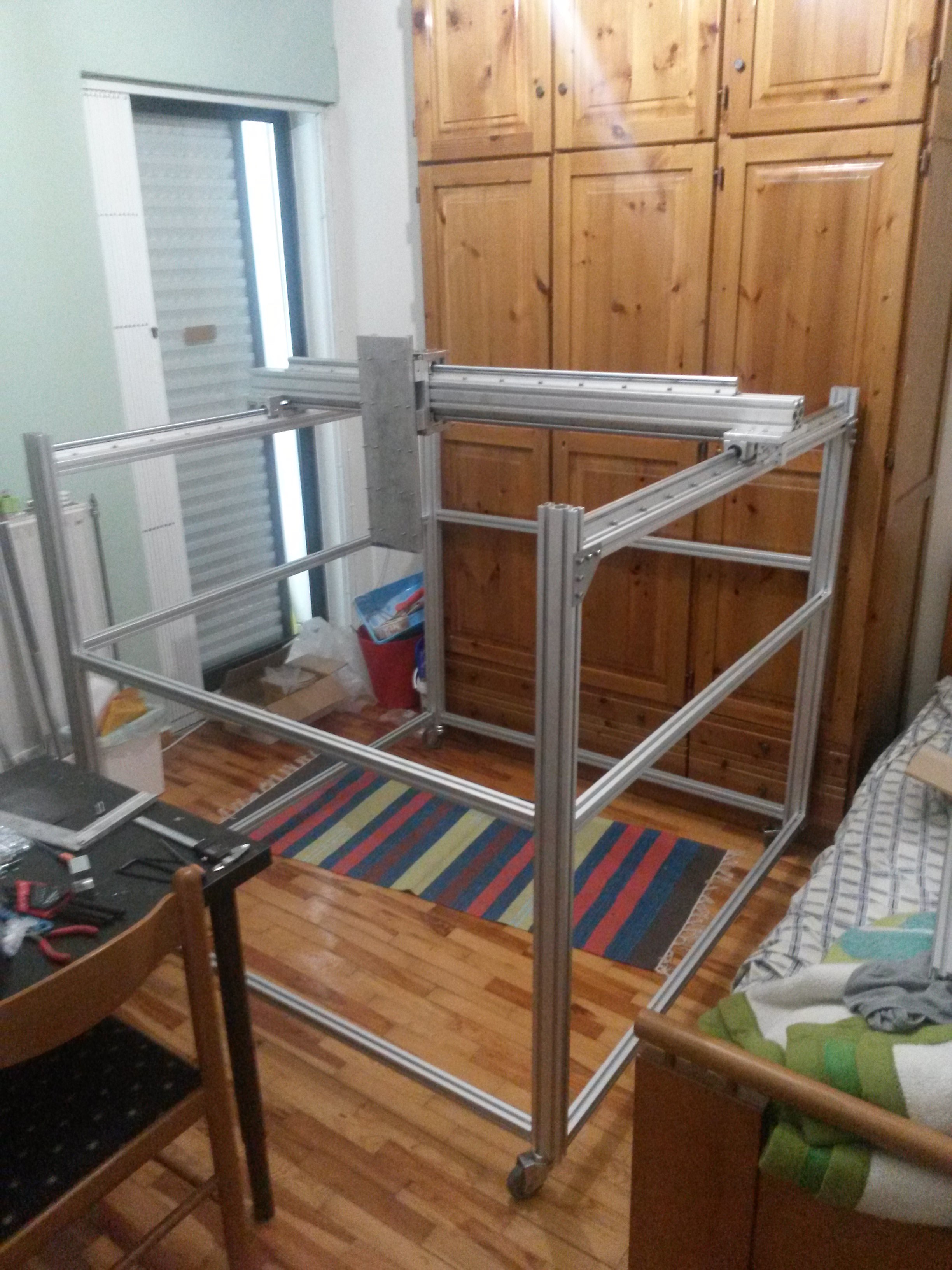
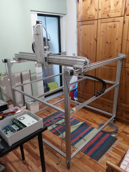
A couple of weeks ago I have finished building the latest version of my CNC machine. In size, this new CNC machine is a few cm bigger than the typical small square IKEA tables. The purpose of building it, was to have a test-bed for improvements, but also to have a CNC at home for making parts for my future projects.
Some of the improvements I have in mind are the integration of more tools for my CNC machines, like laser engraver, tangential knife, etc. Currently the supported tools are Kress spindles and also those typical Chinese…DC powered…air cooled…shitty spindles for milling, as well as Mk8 extruders for 3D printing.
Another thing that needed testing was some new features and improvements I was planing for the firmware of the controller and the controller itself. One of them was to improve the communications between the PC and the controller, by implementing a command queue on the controller. This allows the CNC machine to execute g-code commands one right after the other. In previous versions of the firmware the controller was executing a command and then it was waiting for a few milliseconds for the next command to arrive.
So after implementing this command queue, I had the opportunity to also do another sub-project I had in mind for quite some time, which was to make the CNC play music. I wrote a small python script, that translates note-duration pairs into feed-rate and distance pairs and generating a g-code file that when executed makes the CNC sound like a playing music. I uploaded a small video of a little demonstration on YouTube, which you can see bellow.
Enjoy! 🙂
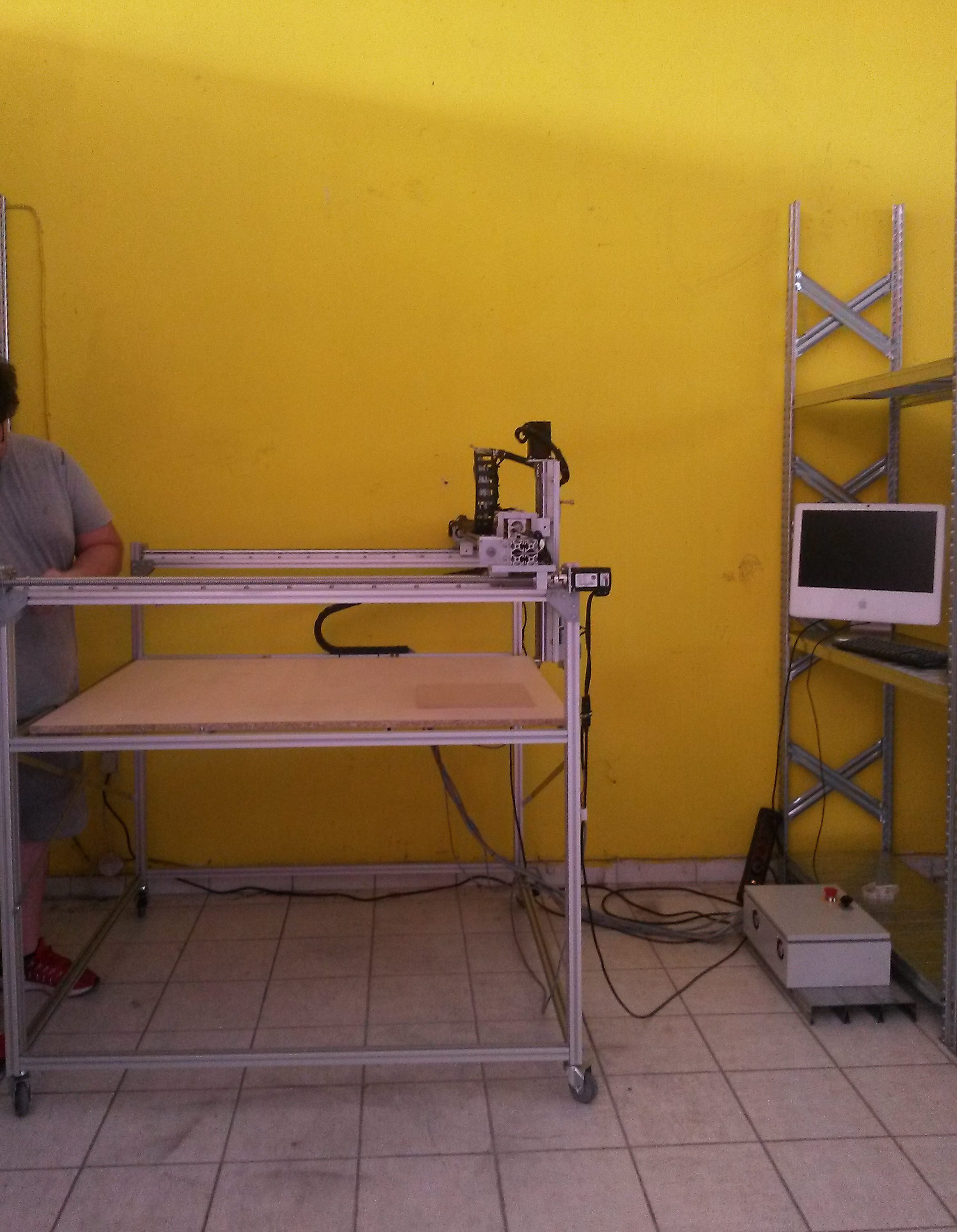
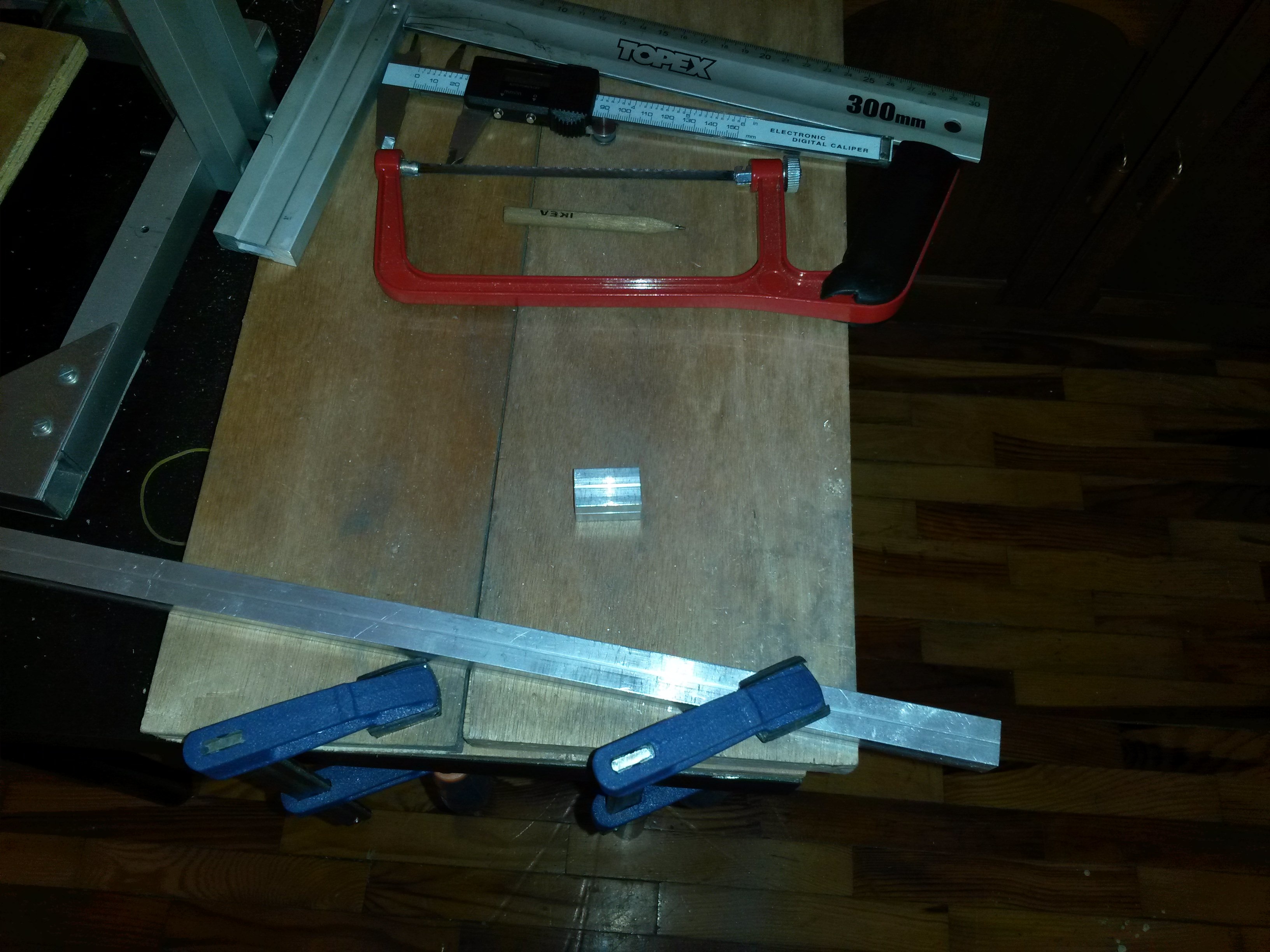
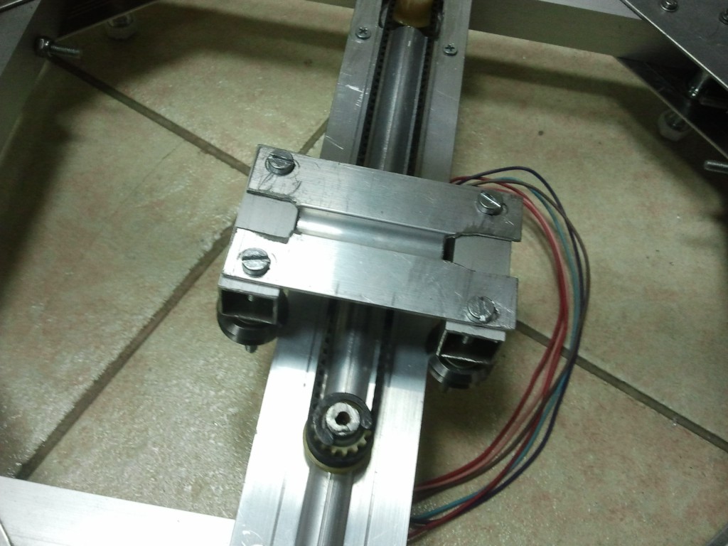 Picture1
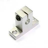 Picture2
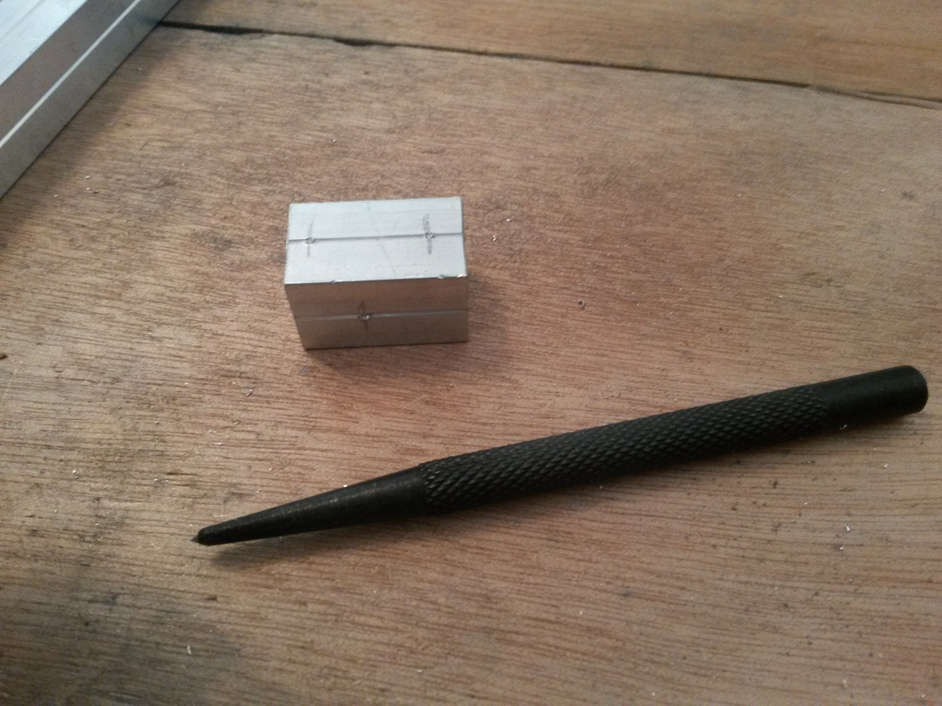
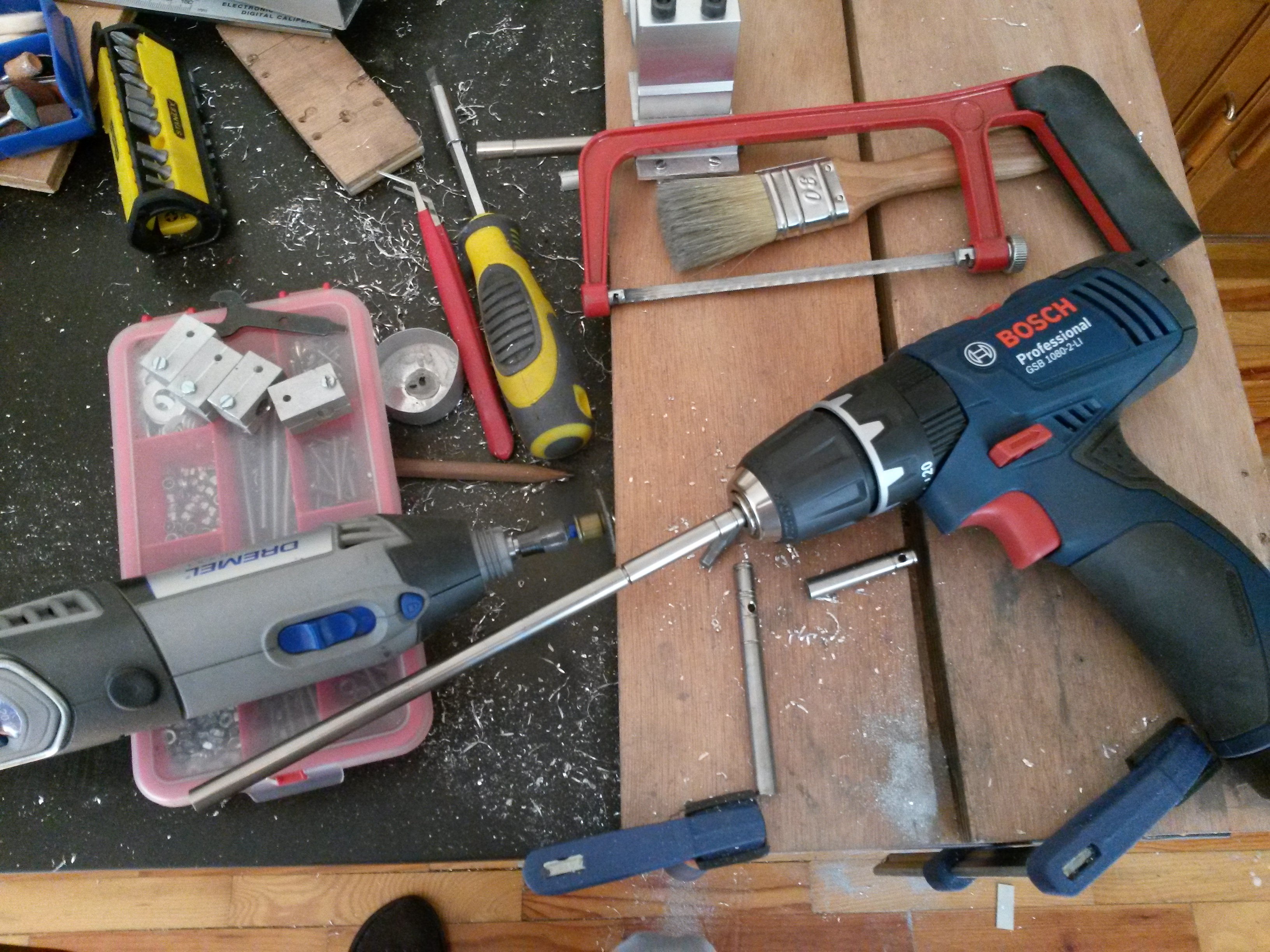
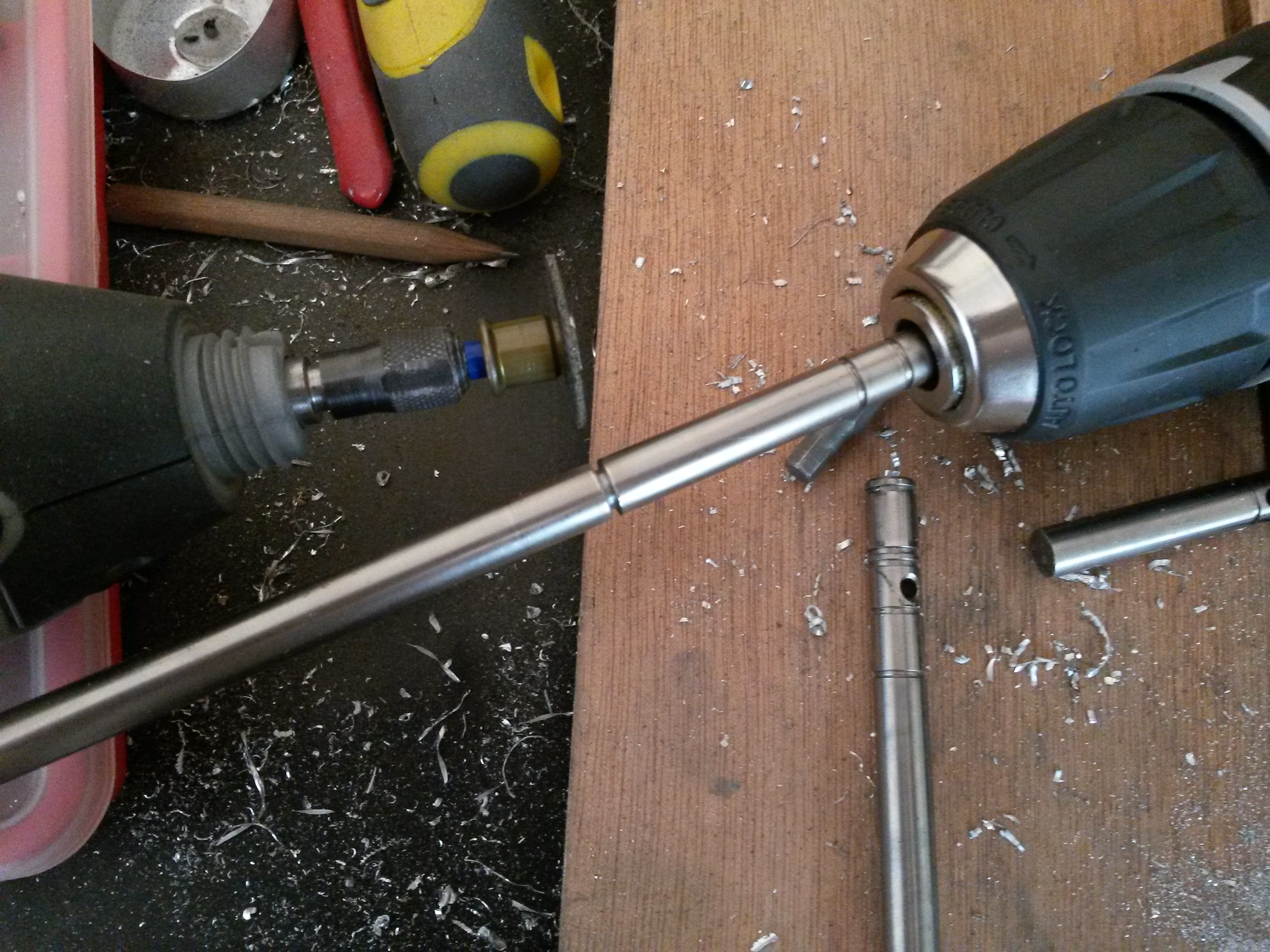
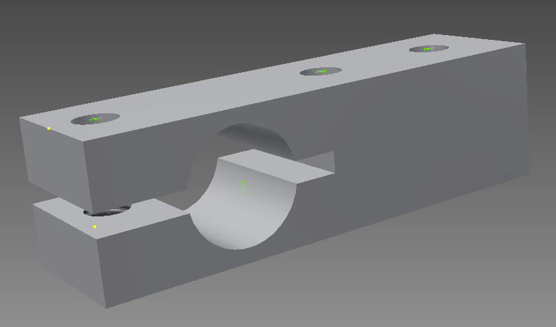 Picture3