Making of a 8mm rod holder Posted on November 7, 2015 8:02 pm Edit This Categories: CNC,DIY
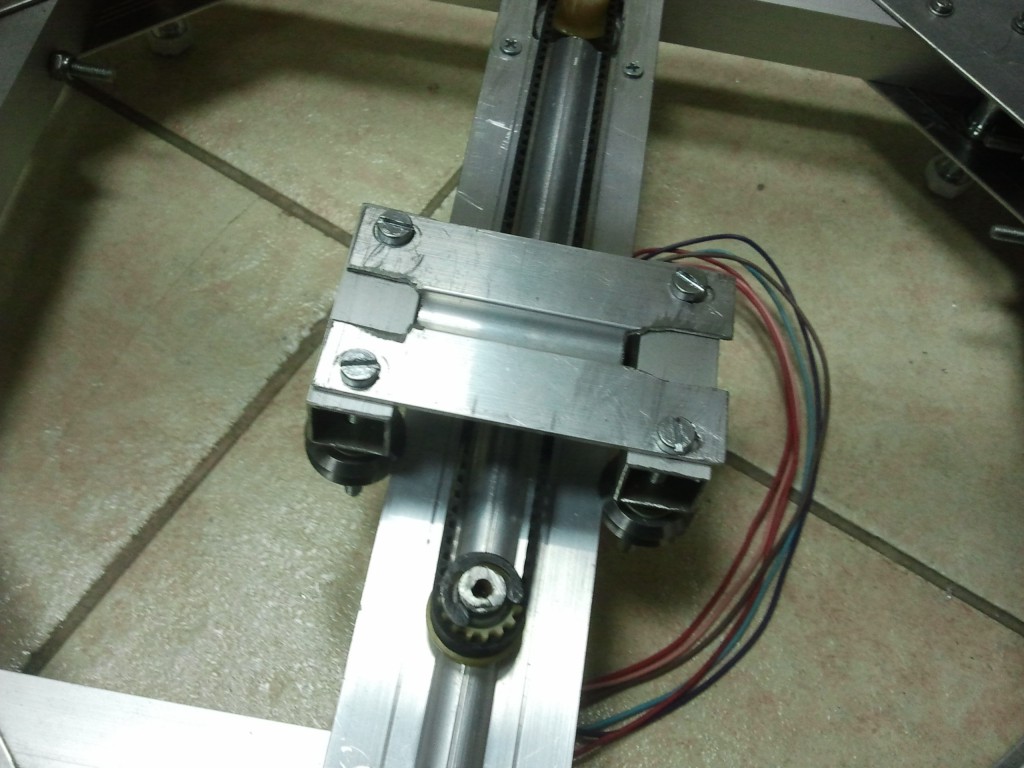
One of the upgrades I am making to my CNC is the change of the linear guide system, from a edge track with V-groove bearings like the one shown in Picture1, to a 8mm steel rod with LM8UU linear bearing.
 Picture1
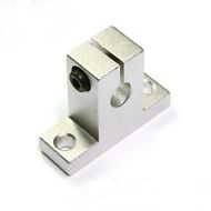
The 8mm steel rods serve as the track for the LM8UU linear bearings and need to be secured to the CNC usually from their two ends. Given that the 8mm rods are have a round “profile” it is not easy (or nice) to just drill them and secure them with a screw. Instead they need some kind of a holder Like the one in Picture2, which is screwed on the frame and then the the 8mm rod is attached to them. You can buy one of these from ebay for a couple of EUR, but that has two disadvantages, first that you will have to wait several days for them to get delivered and second and most important…you loose all the fun of making them yourself. Although it is not too much fun if you don’t have the right tools (like a descent standing drill for example).
 Picture2
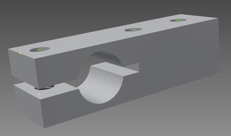
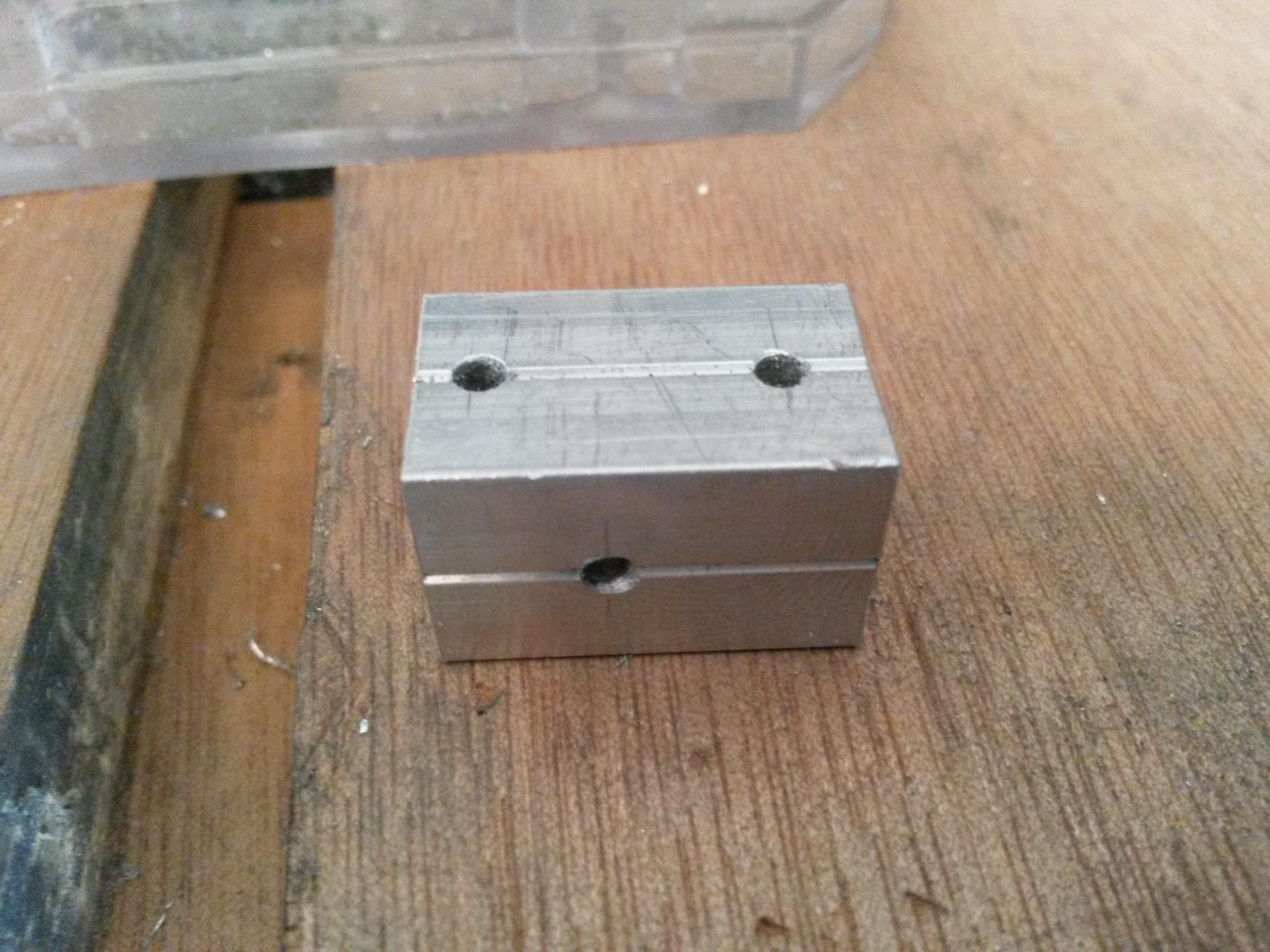
So anyway, I decided to design and build my own holders, despite the lack of any standing drill in my toolset. The initial design is shown in Picture3. In the design you can see a large 8mm hole, where the steel rod is inserted. There is a cut parallel to the 8mm hole, which allows the hole to be tightened using a screw, in order to tightly secure the steel rod. On the left side of the image you can see where that screw is fitted. The bottom half of that hole is threaded (M3 size thread). The other two holes on the right of the picture 3 are for fastening the holder on the frame.
 Picture3
I made the first 4 holders, which are for the 2 steel rods used for the Y-axis, but later on I decided that I could make the part a bit shorter and get rid of the one of the two holes used for fastening it on the frame.
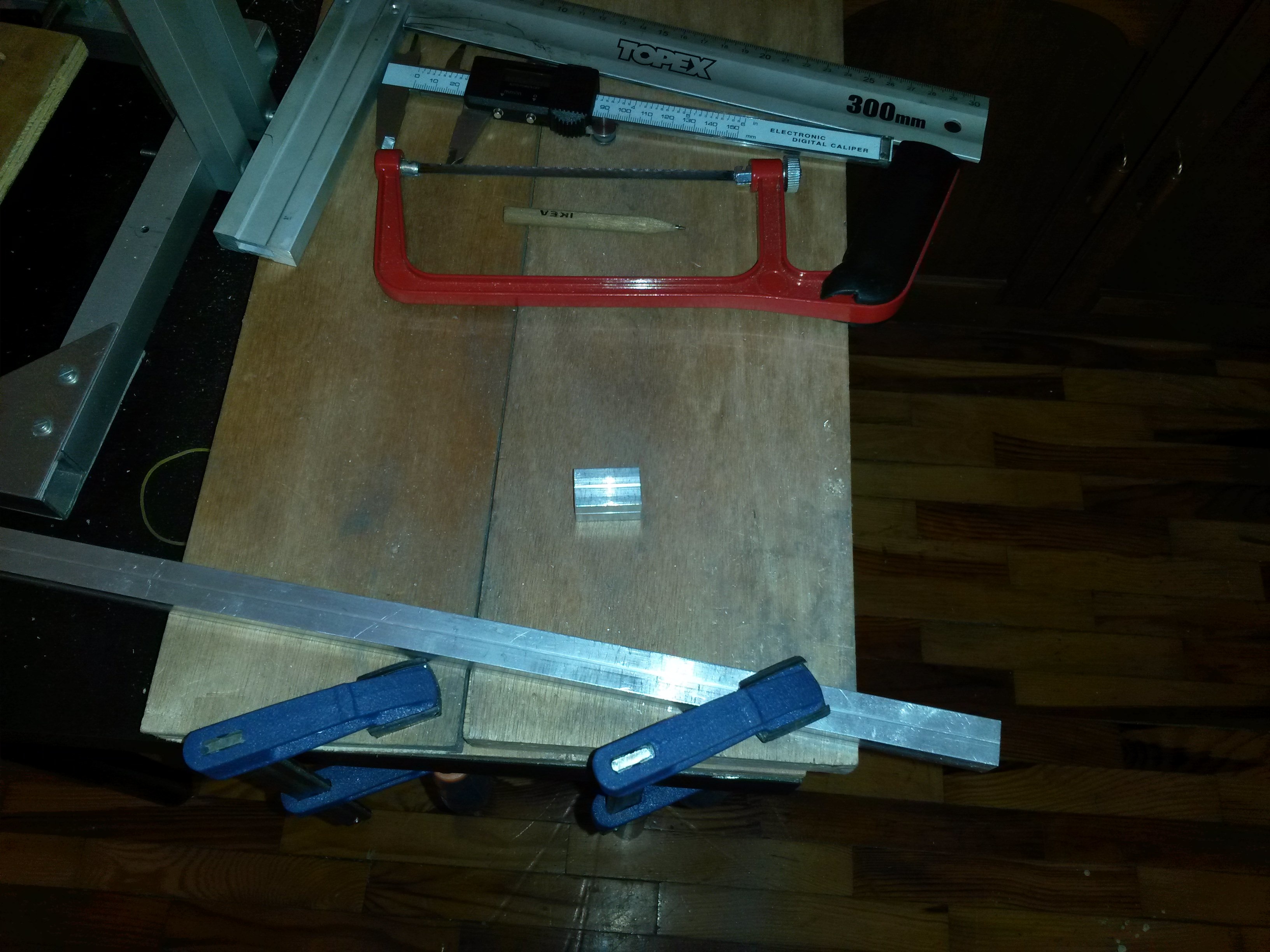
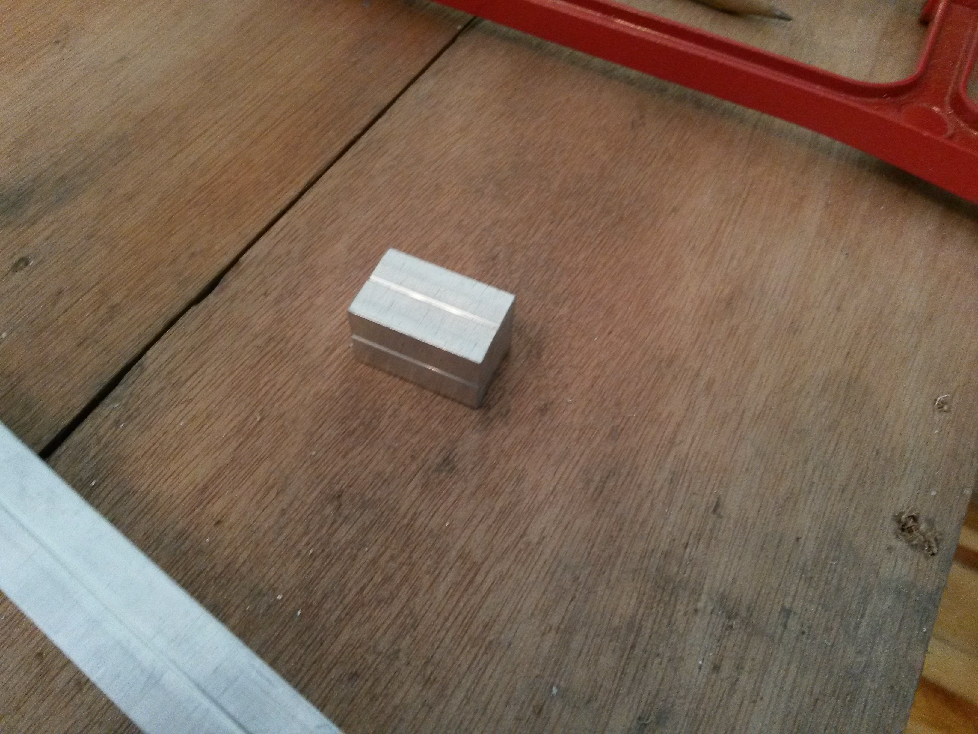
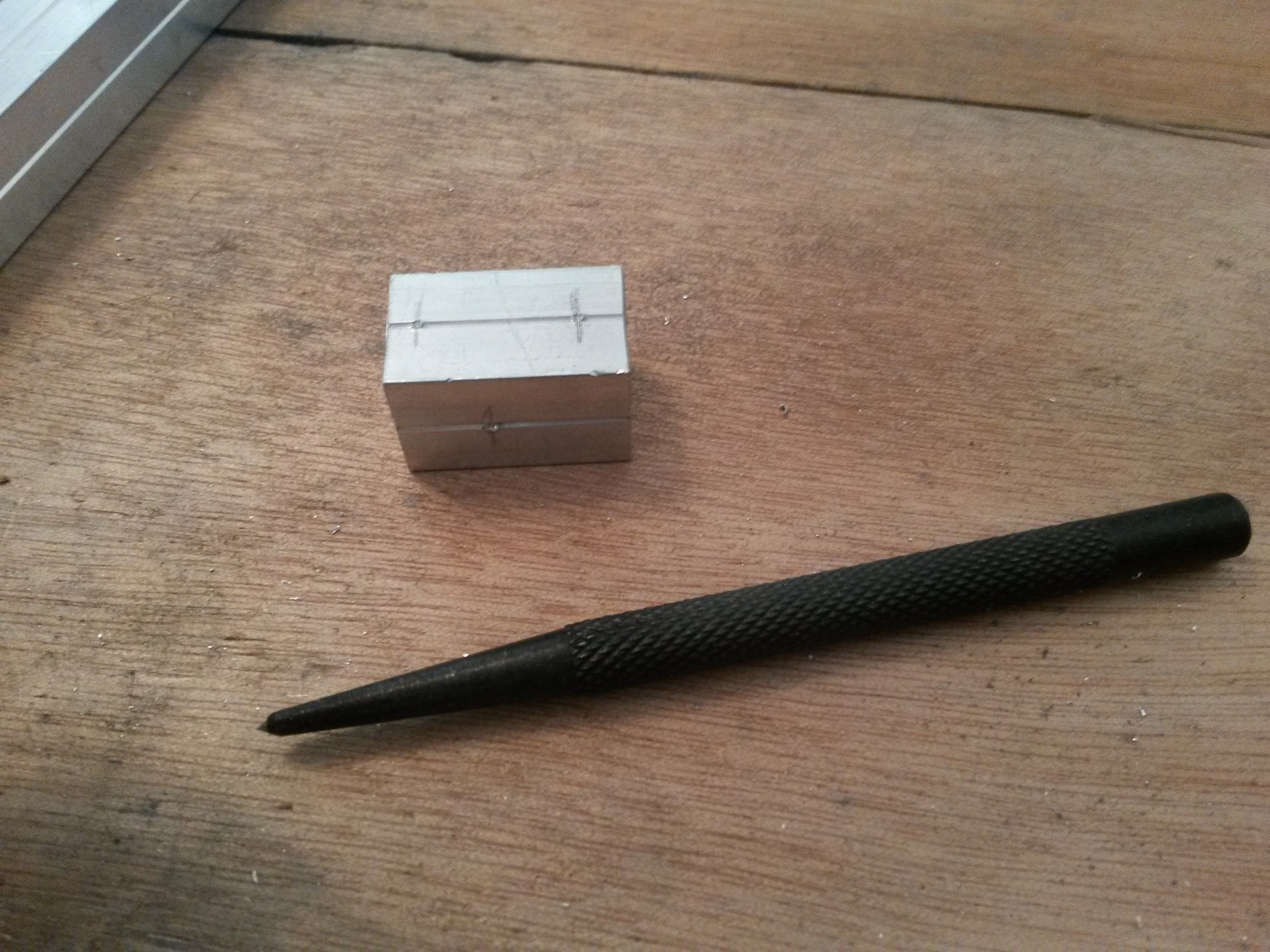
I start making the part by cutting a 25mm long piece of 15x15mm solid aluminum profile. I use a small saw for metal to do this. Then the centers of the holes are marked with a caliper and pencil and finally with a punching tool.
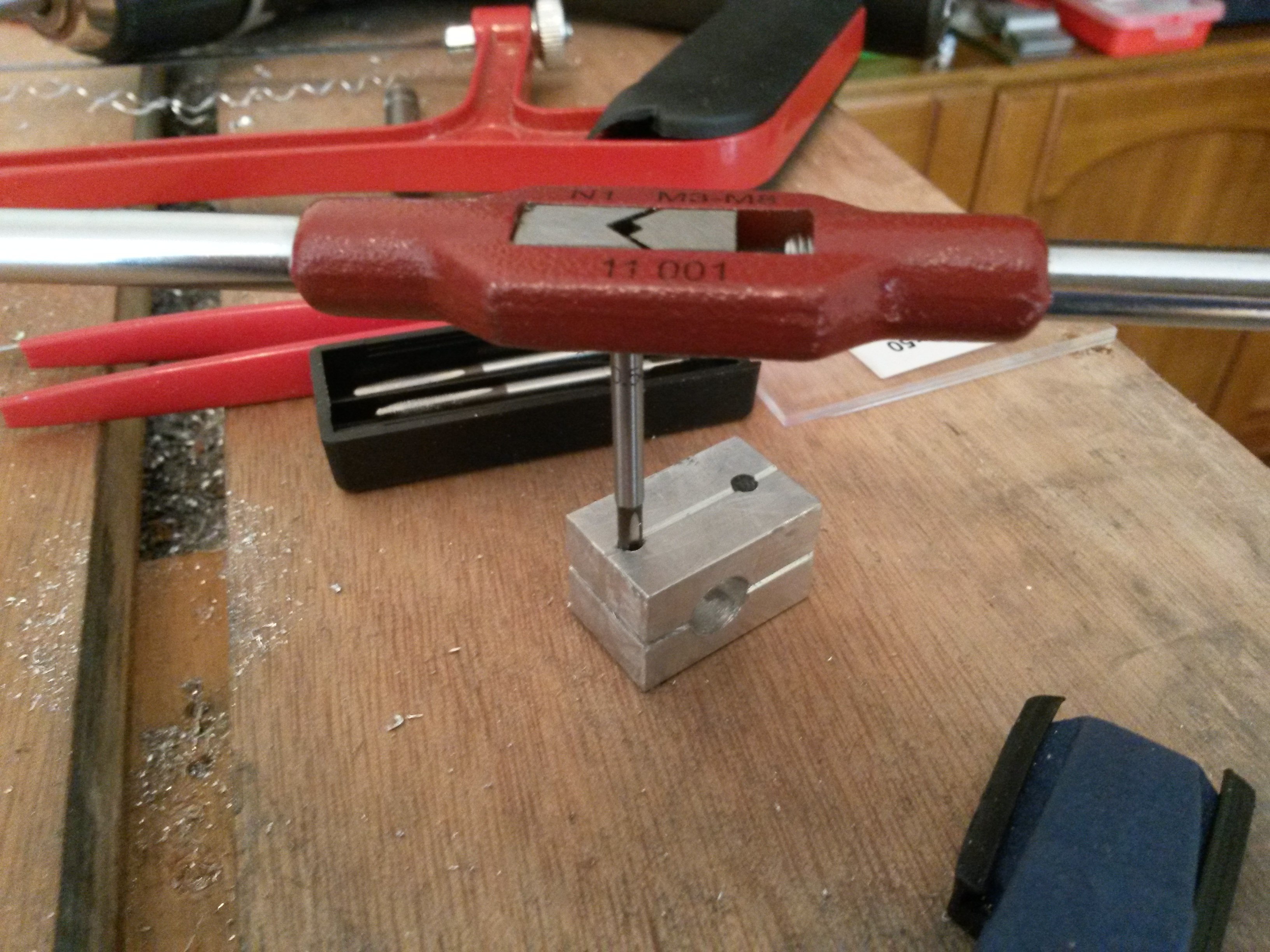
I then use my improvised jig that uses a dremel and a dremel router base, in order to be able to make the holes as perpendicular as possible to the part. Unfortunately the dremel router base is not as precise as I wanted, but the result is acceptable I believe. One of the two handles of the dremel router base is a screw, which allows you to lock it to a certain depth. I noticed that it improves things a bit if you make this as tight as possible (just to the point that you can barely can plunge it down).
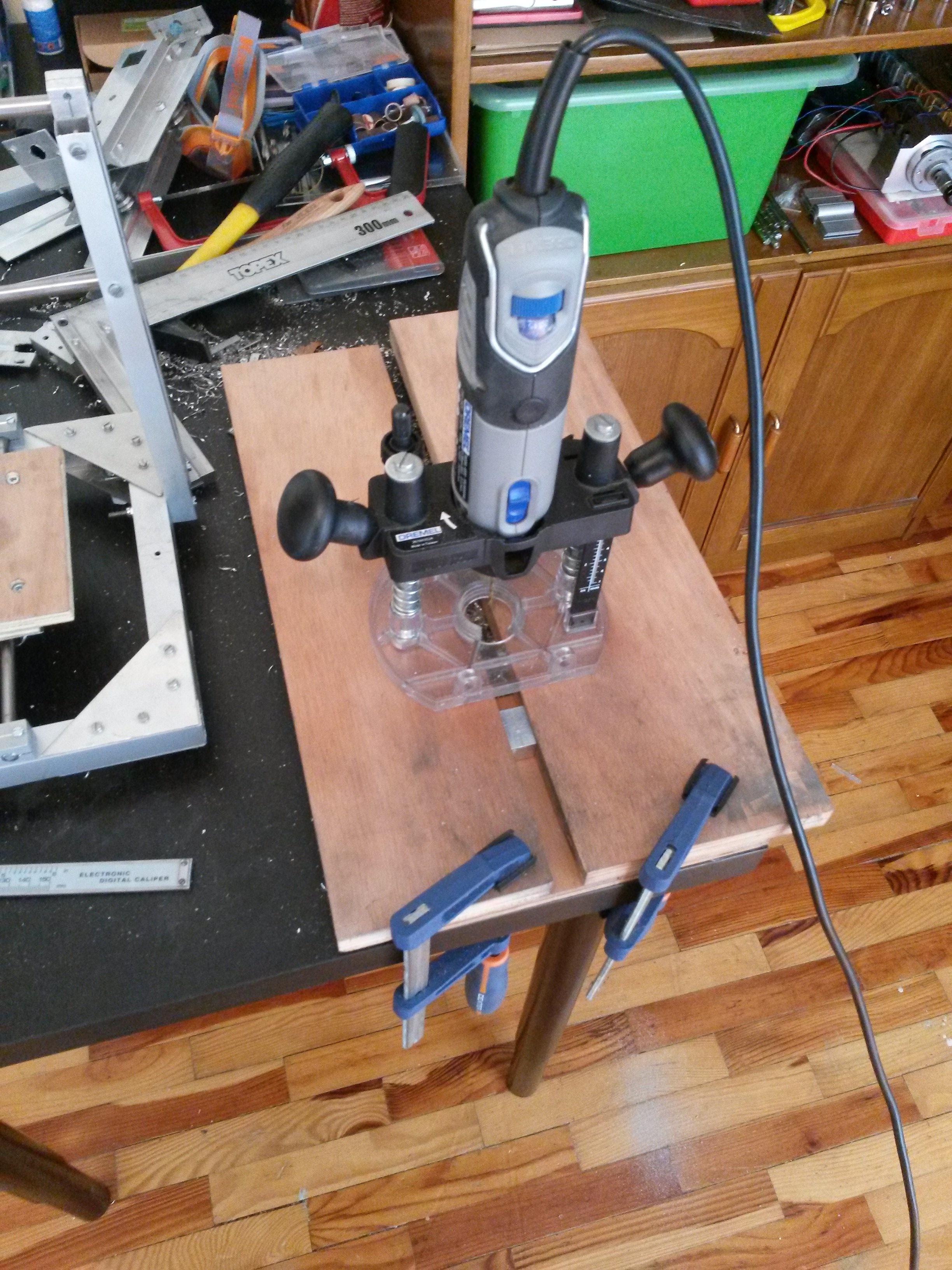
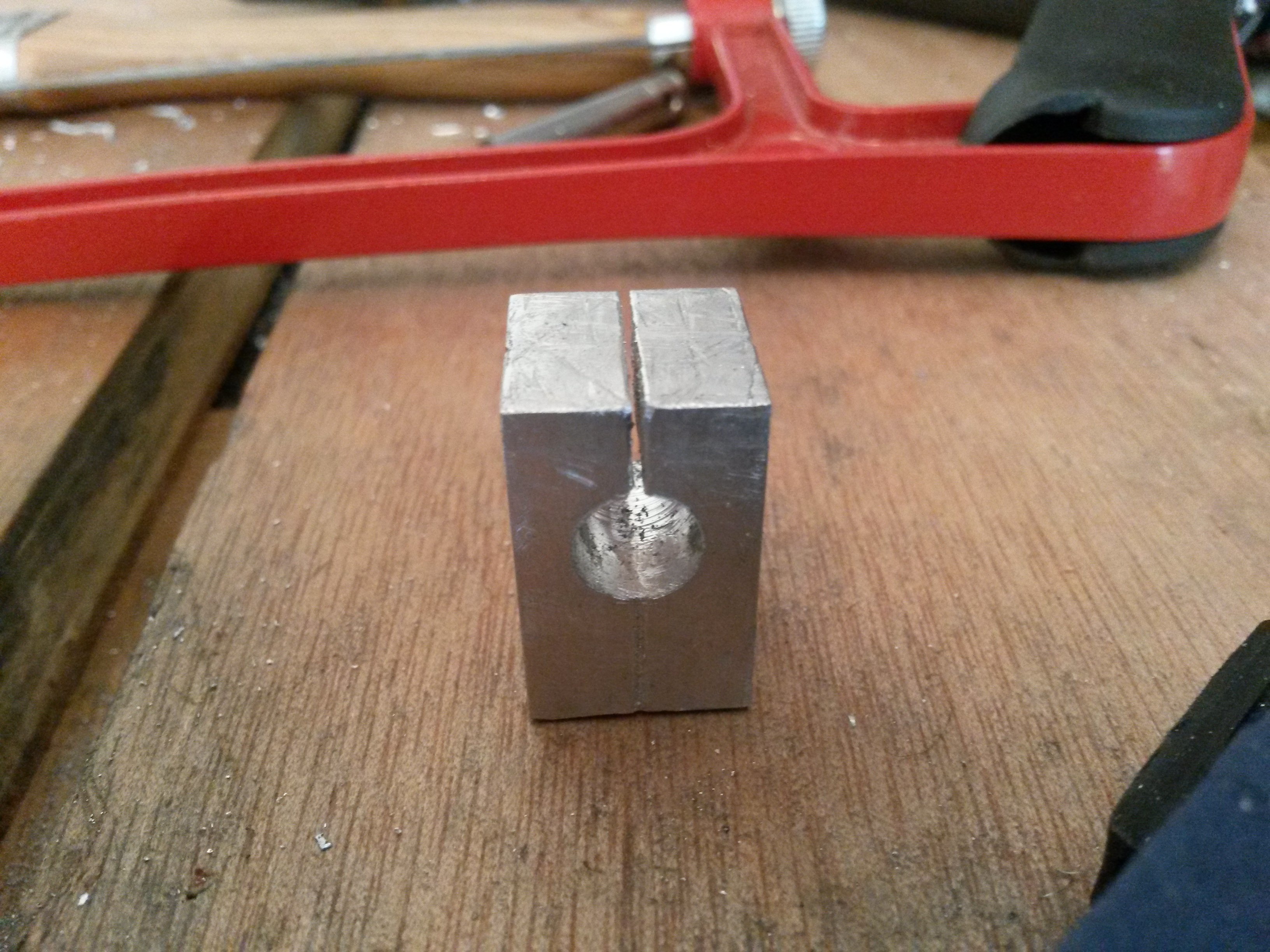
The holes are initially drilled to 2.5mm. After that the holes are widened to 3mm, except the hole that is used for the screw that squeeze the “jaws” of the part, which is only drilled halfway to 3mm. This is done because the other half will be taped for the M3 threads. The 3mm is the maximum I can do with my dremel. So the jig is useless from that point on and I just use a simple hand drill, to widen the big hole for the 8mm rod from 3mm to 4mm, then 5mm, then 6mm, then 7.5mm and finally to 8mm. Luckily the initial 3mm hole is a good guide and the hole remains perpendicular (at least perpendicular enough).
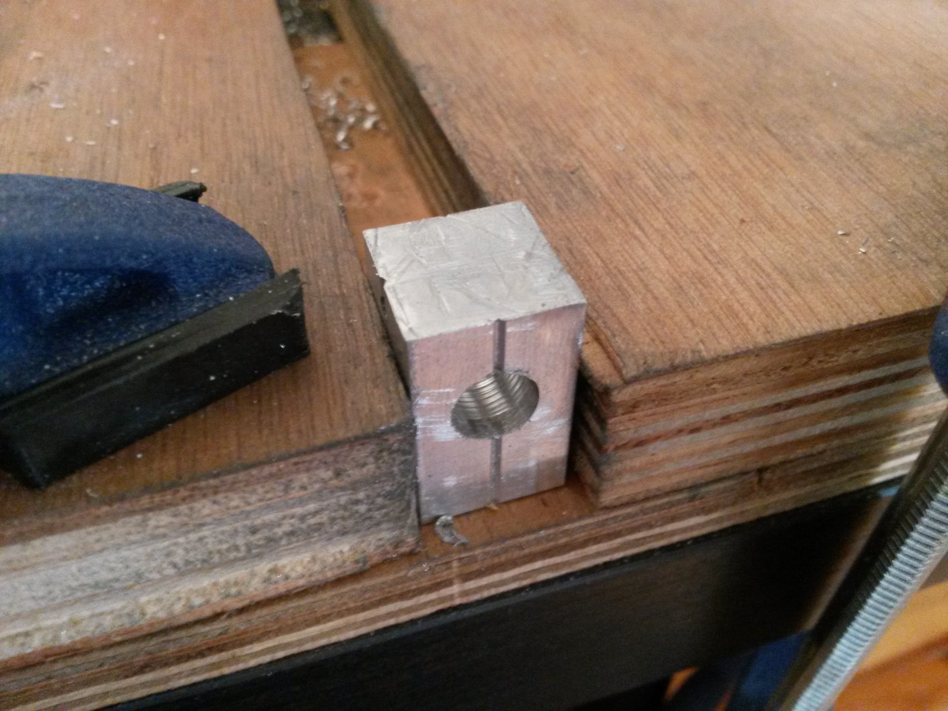
Next I use again the hand saw to cut the slot parallel to the 8mm hole and finally I make the M3 threads for the tightening screw.
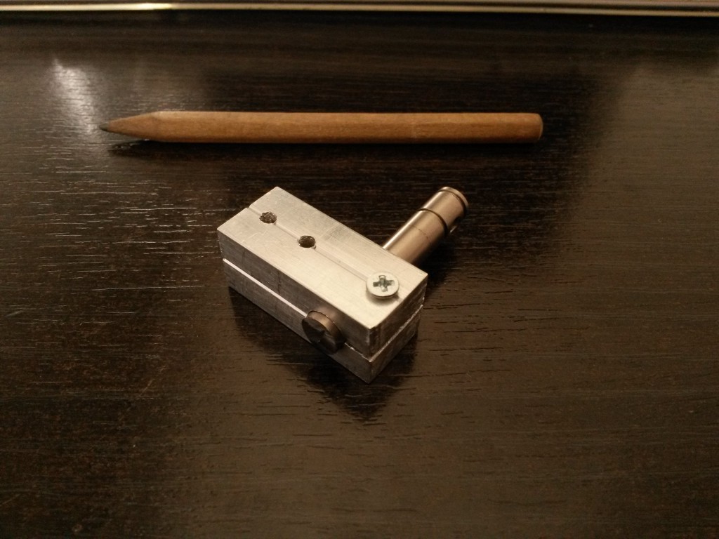
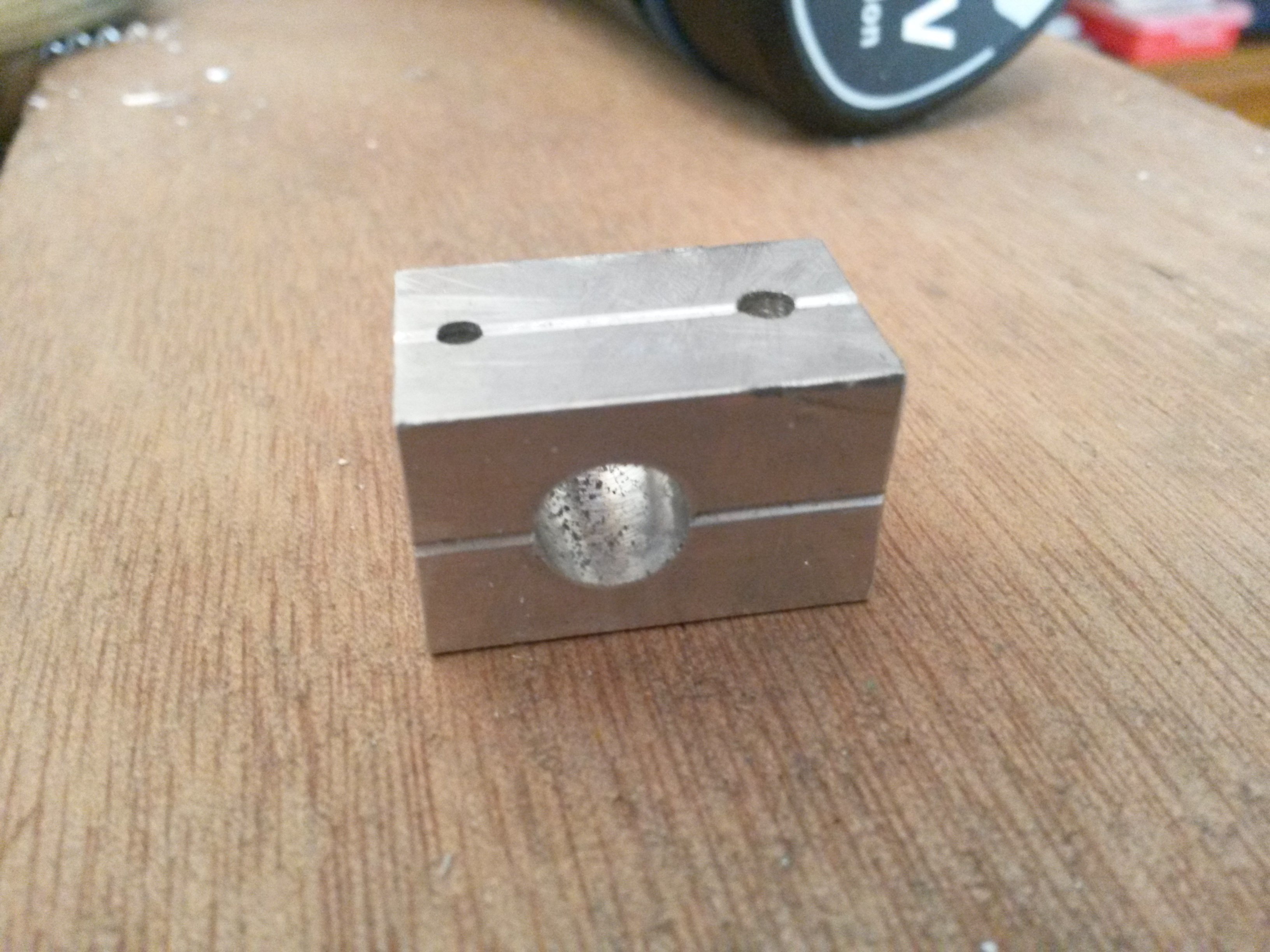
After a final sanding and filing the holder is ready!
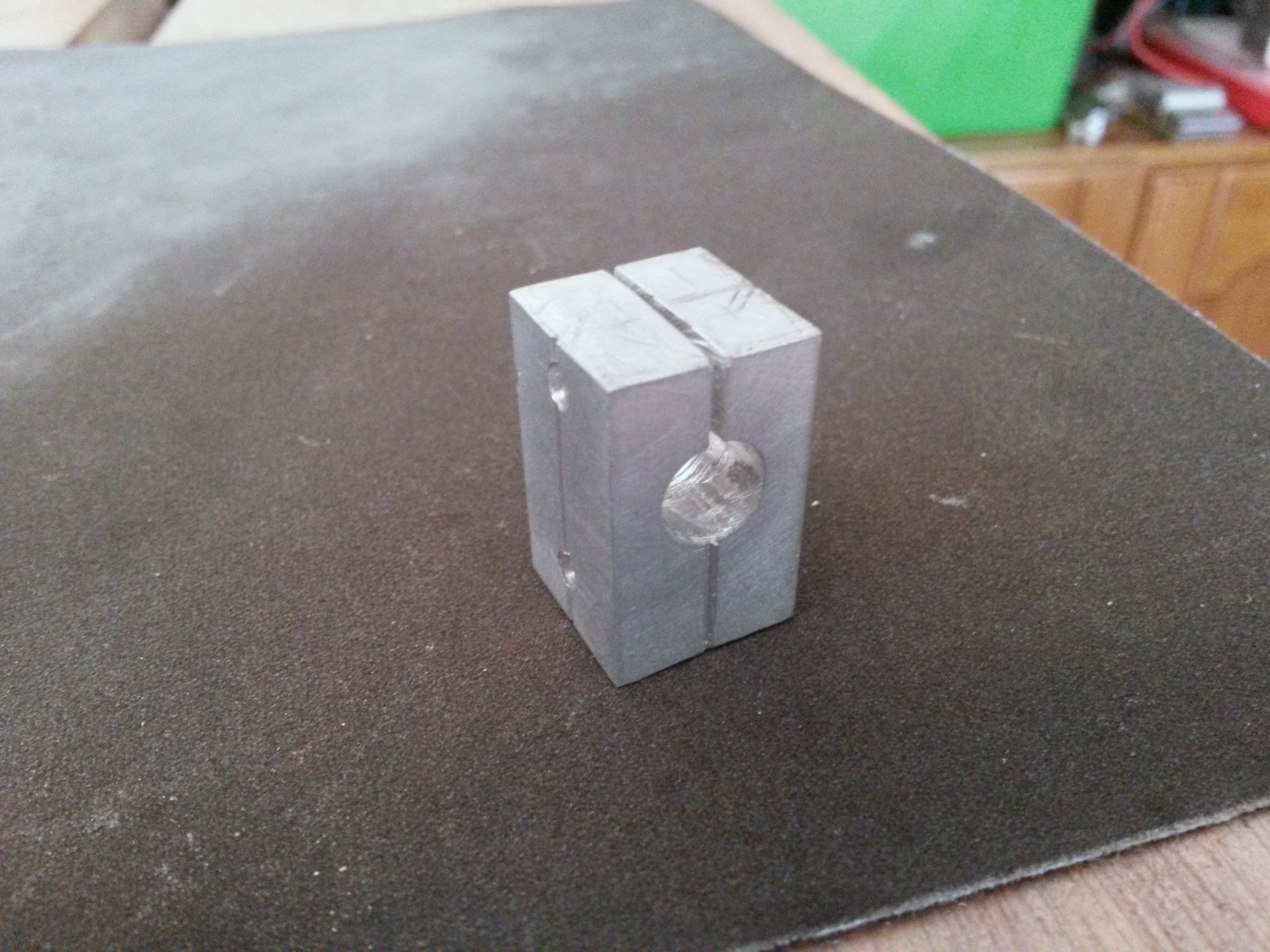
This is the first holder I made, using the old design with the 2 holes for fastening to the frame.